Refer to the exhibit.
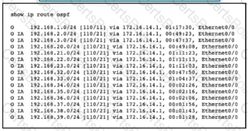
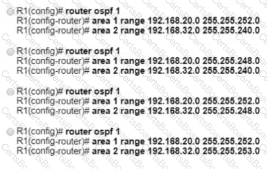
An engineer applied the summarization configuration on R1 for four networks (192.168.20.0/24 to 192.168.23.0/24) in area 1 and eight networks (192.168.32.0/24 to 192.168.39.0/24) in area 2 to stop the flooding of all the customer routes. While checking the routing table of R2, the engineer noticed that R1 is still sending only specific routes to R2. Which configuration should the engineer apply on R1 to summarize routes?
Refer to the exhibit.

Router 1 has attempted to establish a Cisco MPLS TE tunnel to router 2, but the tunnel
has failed. Which statement about this configuration is true?
An engineer is troubleshooting a connectivity issue across the MPLS network and is verifying the forwarding behavior of packets. Which table does the engineer look at to verify the forwarding behavior of an IP packet as it enters the MPLS network at the ingress LSR?

Refer to the exhibit. After a recent network implementation project, customer A is performing stress testing to verify network redundancy at the branch office connected to R4. When the link from R2 is shut öown as shown, the SLA tracking object fails and the cost of the link between R2 and R4 increases to 100. However, a traceroute operation from a PC in the Branch office shows that traffic to HQ is still routed via R2. Which solution corrects the problem and optimizes traffic flow via R3 without creating operational overhead?
Which two conditions must be met before separate ISPs can provide interdomain multicast routing? (Choose
two.)
Refer to the exhibit.

A network engineer applied configuration on R1 to summarize all ISIS routes, but R2 Is still receiving specific routes from R1. The engineer has confirmed that both routers are configured with the correct summarization configuration, but R1 is not sending the correct summary routes. Which configuration must be applied to router R1 to summarize routes within Level 1?

Refer to the exhibit The engineering team noticed route disruptions when DSL subscriber 172.16.20.10 goes offline. In this service provider environment:
The OSPF backbone area is configured to advertise loopback prefixes
The PE routers are running BGP-IPv4 address family in a BGP-free core topology.
The DSL subscriber IP subnet 172.16.20.10/32 is redistributed in BGP on PE1
Which configuration on PE1 resolves the issue?


Refer to the exhibit. CE1 and CE2 use connectivity over the service provider cloud to reach CE3 In the event of a link failure in the service provider cloud which BGP feature relies on IGP convergence to quickly assist in the installation of a backup path?
Guidelines
This is a lab item in which tasks will be performed on virtual devices.
Refer to the Tasks tab to view the tasks for this lab item.
Refer to the Topology tab to access the device console(s) and perform the tasks.
Console access is available for all required devices by clicking the device icon or using the tab(s) above the console window.
All necessary preconfigurations have been applied.
Do not change the enable password or hostname for any device.
Save your configurations to NVRAM before moving to the next item.
Click Next at the bottom of the screen to submit this lab and move to the next question.
When Next is clicked, the lab doses and cannot be reopened.
Topology

Tasks
Configure and verify an OSPF neighbor adjacency between R1 and R2 in OSPF area 0 according to the topology to achieve these goals:
1. R1 pings the Loopback0 interface of R2. Use interface-level configuration to complete this task.
2. R2 pings the Loopback0 interface of R1. Use interface-level configuration to complete this task.
3. R2 receives a single summary route 172.16.100.0/22 for networks 172.16.100.0/24, 172.16.101.0/24, and 172.16.103.0/24.


TESTED 19 Apr 2025